
Introduction
In a VMware vSphere environment, Tanzu Kubernetes Grid (TKG) makes it easy to build a Kubernetes environment. This article uses the standalone, multi-cloud-compatible TKGm edition. NSX ALB continues to use the Essentials license. This article covers the steps to build a Management cluster and Workload cluster as part of a Tanzu Kubernetes Grid deployment.
Last time
This article assumes that NSX ALB has already been built and that the preparation steps and Bootstrap machine setup are complete. If you have not completed those steps yet, refer to the article below first.
Environment
| Environment |
|---|
| VMware ESXi 8 |
| VMware vCenter 8 |
| Tanzu Kubernetes Grid 2.1.1 |
| NSX Advanced Load Balancer 22.1.3 |
Prerequisites
- Ability to build VMware ESXi and manage the datacenter with vCenter
- Two or more VLAN networks are available.
- In this environment, I prepared a management network, VM Network (VLAN0), and a Kubernetes network, VLAN100 (VLAN100).
- Servers and storage with sufficient resources
- NSX ALB uses CPU: 8, RAM: 24GB, ROM: 128GB.
- Depending on the requirements, 4 to 12 virtual machines with CPU: 2, RAM: 8GB, and ROM: 40GB are deployed as Kubernetes nodes.
Building a Management cluster
Launching the web UI for deployment
You can deploy by writing YAML or by using the web UI. This article uses the web UI to create a Management cluster.
-
Connect to the Bootstrap machine by SSH using Tera Term or a similar tool, and log in as the standard user created in the previous article.
-
Run the following command to start the web UI.
MuNeNiCK [ ~ ]$ tanzu management-cluster create --ui --bind=0.0.0.0:8080 --browser=none

Validating the pre-requisites...
Serving kickstart UI at http://[::]:8080- Open a browser and access
https://<Bootstrap machine IP address>:8080.
Deploying the Management cluster
Deployment destination selection
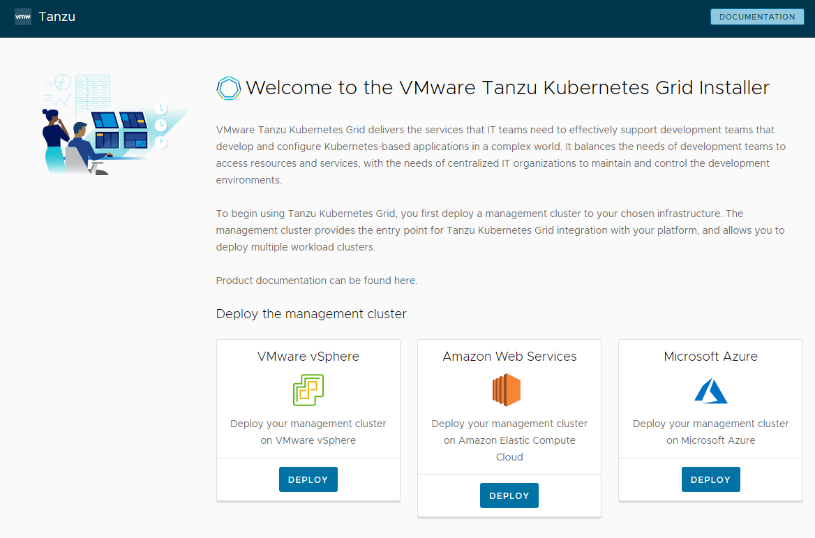
- After accessing the web UI, select the deployment destination. This article uses “VMware vSphere”, so click “Deploy”.
Configuring IaaS Provider
-
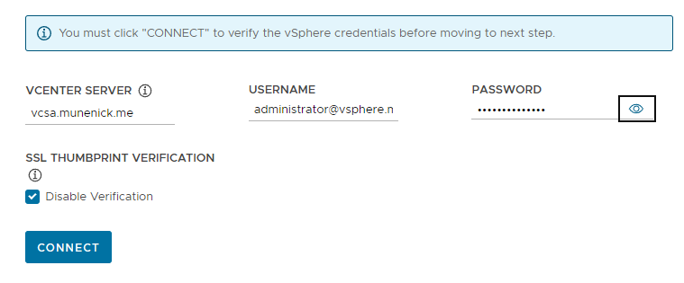
Set the following items and click “CONNECT” to connect to vCenter Server.
- VCENTER SERVER: Specify the IP address or FQDN of vCenter Server.
- USERNAME: Enter the vCenter administrator account name.
- PASSWORD: Enter the vCenter administrator password.
- SSL THUMBPRINT VERIFICATION: Check this if vCenter uses a self-signed certificate.
-
You can specify the deployment method. “CONFIGURE VSPHERE WITH TANZU” is TKGs, which is deployed as part of the vSphere environment. “DEPLOY TKG MANAGEMENT CLUSTER” is TKGm, which builds a standalone multi-cloud cluster. Click “DEPLOY TKG MANAGEMENT CLUSTER” to build TKGm.
-
When you connect to vCenter, you can additionally set the following items.
- DATACENTER: Specify the datacenter where the cluster will be deployed.
- SSH PUBLIC KEY: Specify the SSH key created when setting up the Bootstrap machine in the previous article.
After completing these settings, click “NEXT”.
Configuring Cluster Settings
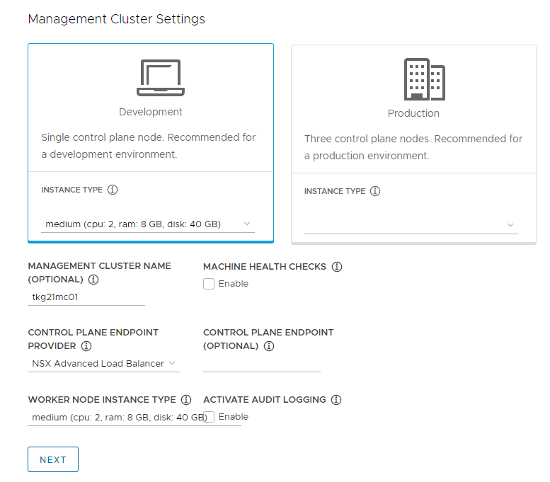
- Set the following items.
-
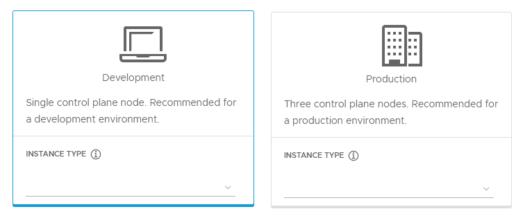
Deployment type: Choose either “Development” or “Production”. Use “Development” for a development environment and “Production” when high availability is required. This article selects “Development”.
- Development: Two virtual machines, one control-plane node and one worker node, are created.
- Production: A total of 6 virtual machines, 3 control-plane nodes and 3 worker nodes, are created.
-
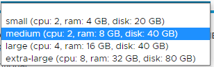
INSTANCE TYPE: Choose one of four specifications for the nodes deployed in the Management cluster: “small”, “medium”, “large”, and “extra-large”. The selected instance type is applied to the number of virtual machines specified by the deployment type. This article selects “medium”.
- small: cpu: 2, ram: 4GB, disk: 20GB
- medium: cpu: 2, ram: 8GB, disk: 40GB
- large: cpu: 4, ram: 16GB, disk: 20GB
- extra-large: cpu: 2, ram: 4GB, disk: 20GB
-
MANAGEMENT CLUSTER NAME: Specify the name of the Management cluster to deploy. This article uses “tkg21mc01”.
-
MACHINE HEALTH CHECKS: Performs health checks on deployed nodes.
-
CONTROL PLANE ENDPOINT PROVIDER: Choose either “kube-vip” or “NSX Advanced Load Balancer”. This article uses “NSX Advanced Load Balancer”.
-
CONTROL PLANE ENDPOINT: Specify the VIP address of the control-plane node. This article leaves it unset.
-
WORKER NODE INSTANCE TYPE: Specify the node size used for the Workload cluster. The available items are the same as INSTANCE TYPE.
-
ACTIVATE AUDIT LOGGING: Enable audit logging.
-
The settings in this article are shown below. This is only an example, so change it to match your environment and requirements.
After completing all settings, click “NEXT”.
Configuring VMware NSX Advanced Load Balancer
-
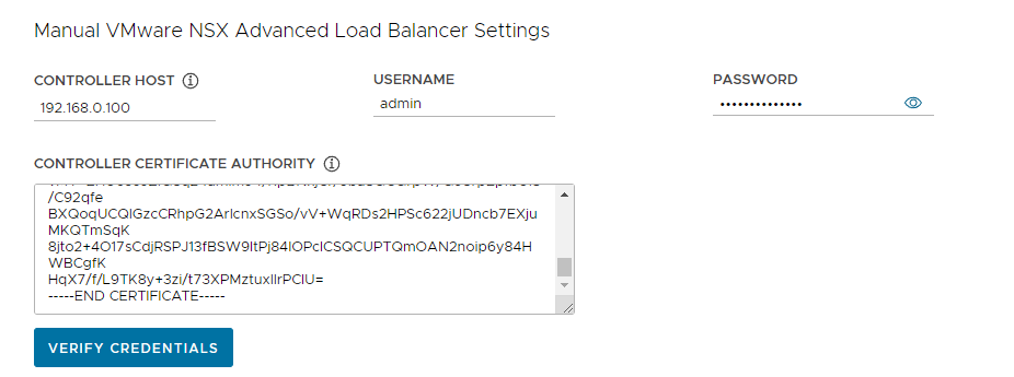
Connect to NSX ALB by setting the following items and clicking “VERIFY CREDENTIALS”.
- CONTROLLER HOST: Specify the IP address or FQDN of NSX ALB.
- USERNAME: Specify the account name used to log in to NSX ALB. The default is “admin”.
- PASSWORD: Specify the password for the account.
- CONTROLLER CERTIFICATE AUTHORITY: Paste the certificate obtained in Obtain a certificate when building NSX ALB.
-
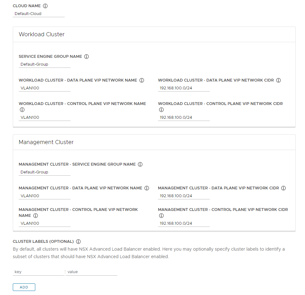
When connecting to NSX ALB, you can additionally configure the following items.
- CLOUD NAME: Specify “Default-Cloud”.
- Workload Cluster: Workload cluster settings.
- SERVICE ENGINE GROUP NAME: Specify “Default-Group”.
- WORKLOAD CLUSTER - DATA PLANE VIP NETWORK NAME: Specify the network for Kubernetes.
- WORKLOAD CLUSTER - CONTROL PLANE VIP NETWORK NAME: Specify the network for Kubernetes.
- WORKLOAD CLUSTER - DATA PLANE VIP NETWORK CIDR: Enter the network address for Kubernetes.
- WORKLOAD CLUSTER - CONTROL PLANE VIP NETWORK CIDR: Enter the network address for Kubernetes.
- Management Cluster: Management cluster settings. These are basically the same as the Workload Cluster settings.
- MANAGEMENT CLUSTER - SERVICE ENGINE GROUP NAME: Specify “Default-Group”.
- MANAGEMENT CLUSTER - DATA PLANE VIP NETWORK NAME: Specify the network for Kubernetes.
- MANAGEMENT CLUSTER - CONTROL PLANE VIP NETWORK: Specify the network for Kubernetes.
- MANAGEMENT CLUSTER - DATA PLANE VIP NETWORK CIDR: Enter the network address for Kubernetes.
- MANAGEMENT CLUSTER - CONTROL PLANE VIP NETWORK CIDR: Enter the network address for Kubernetes.
- CLUSTER LABELS: Labels can be assigned to clusters.
The settings in this article are shown below. They are only examples; if your network design or NSX ALB settings are different, configure them for your environment.
After completing all settings, click “NEXT”.
Metadata settings
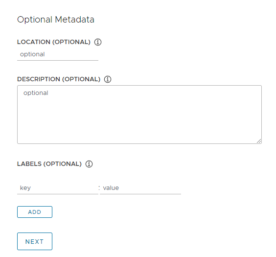
Here you can specify metadata for your Management cluster. This article does not configure any metadata.
After completing the settings, click “NEXT”.
Configuring resources
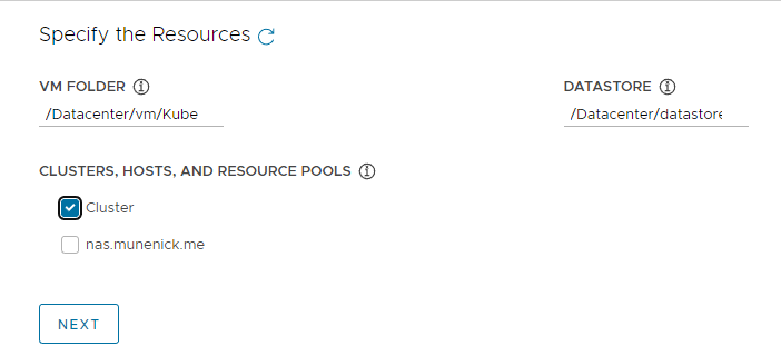
- Set the following items.
- VM FOLDER: Select the folder where you want to deploy the Management cluster. In this article, it is “/Datacenter/vm/TKG/Management”, which is the folder created in Preparation.
- DATASTORE: Specify the destination datastore for the virtual machines deployed as nodes of the Management cluster.
- CLUSTERS, HOSTS, AND RESOURCE POOLS: Specify the cluster, host, and resource pool where the virtual machine to be deployed as a node of the Management cluster will be created.
After completing all settings, click “NEXT”.
Configuring Kubernetes Network
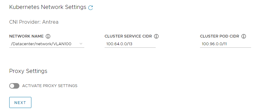
- Set the following items.
- NETWORK NAME: Specify the network assigned to virtual machines deployed as nodes in the Management cluster. You can specify the Kubernetes network here.
- CLUSTER SERVICE CIDR: Network address used by the cluster’s services. You can leave it as the default.
- CLUSTER POD CIDR: Network address used by the Pods in the cluster. You can leave it as the default.
- Proxy Settings: Configure this if a proxy is required for network access. This article leaves it unset.
After completing all settings, click “NEXT”.
Identity Management settings
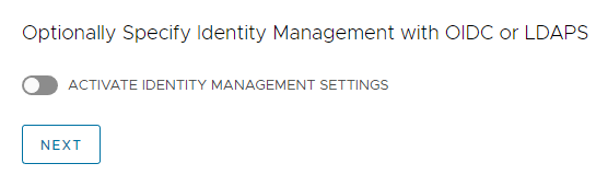
- Configure authentication management with OIDC or LDAP as necessary. This article does not use it, so leave it disabled.
OS Image settings
- Specify the TKR. If the TKR was successfully converted to a template, it appears in the drop-down menu. This article specifies Photon v3.
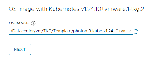
After completing the settings, click “NEXT”.
CEIP Agreement settings
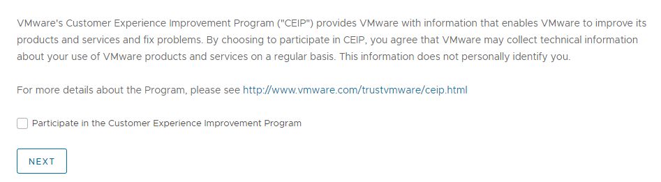
- This setting asks whether to provide CEIP information. This article turns it off.
Check settings
-
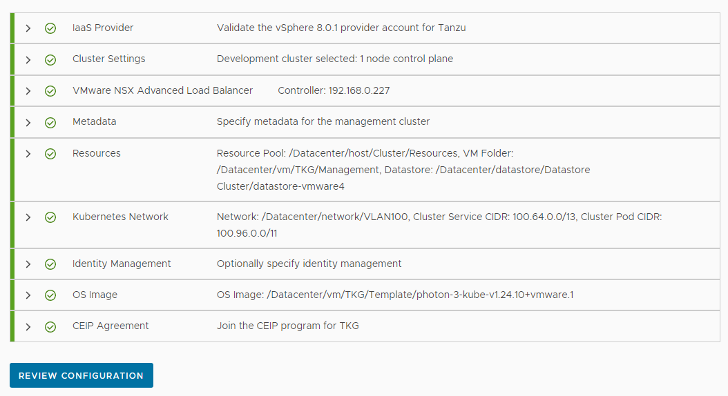
After completing the required settings, each item should have a green check mark and “REVIEW CONFIGURATION” should be available. Click “REVIEW CONFIGURATION”.
-
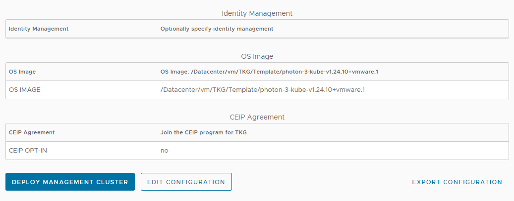
You can confirm the settings at “Tanzu Kubernetes Grid - Confirm Settings”. After confirming that the settings are correct, click “DEPLOY MANAGEMENT CLUSTER”. If you need to change anything, click “EDIT CONFIGURATION”. To save the settings as YAML, click “EXPORT CONFIGURATION”.
Waiting for deployment
When deployment begins, logs are displayed in the web UI and in the SSH session on the Bootstrap machine. Wait until the process completes. Deployment may take around 50 minutes, depending on the environment and settings.
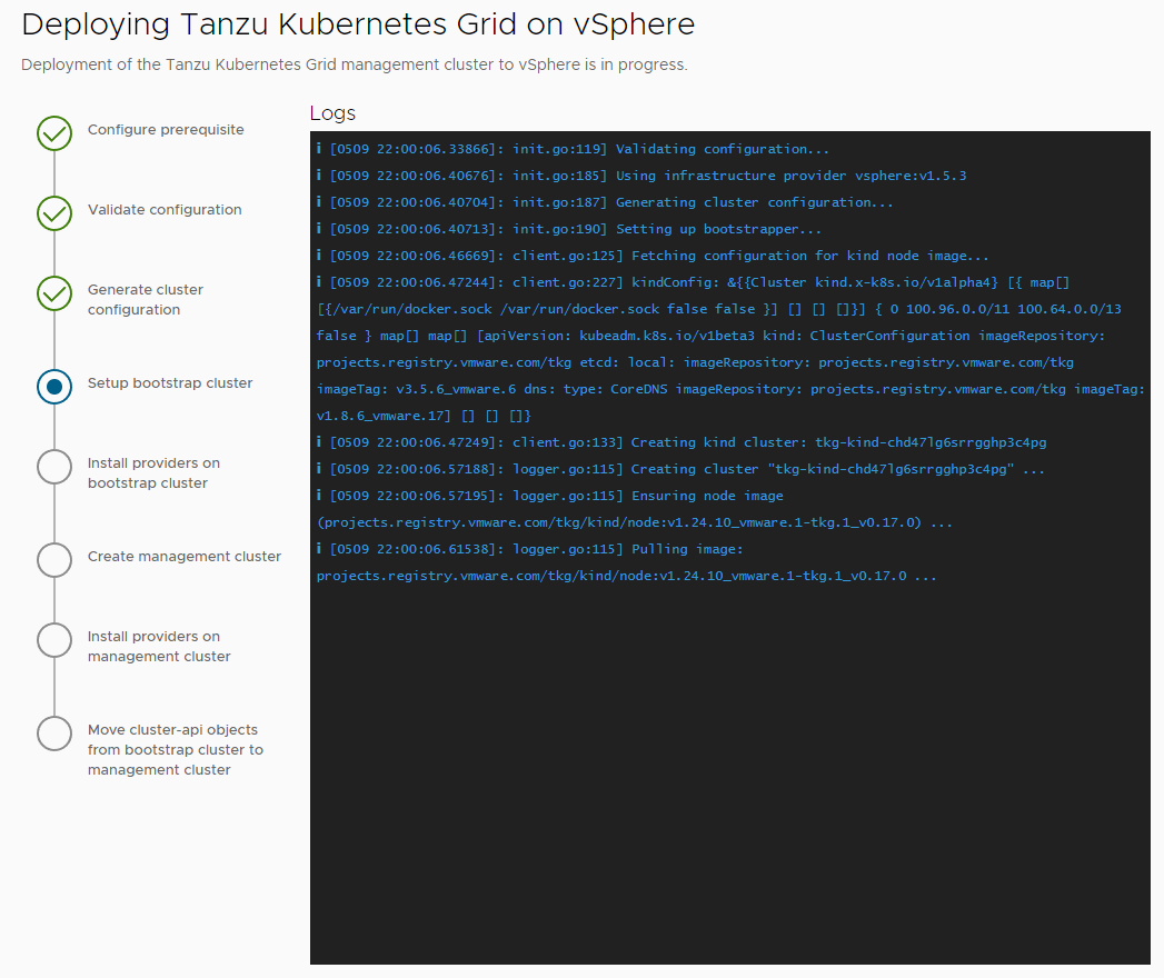
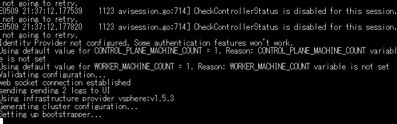
At the bottom of the web UI, CLI commands for running the deployment are displayed. Save them somewhere, because they are useful when retrying after a failed deployment.

If cluster deployment fails
This section covers what to do if cluster deployment fails.
In this example, the “Start creating management cluster…” process failed.
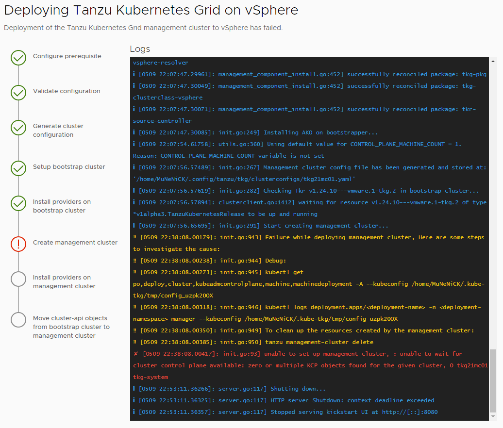
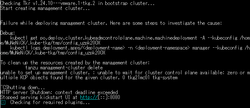
- To identify the cause, run the command under “debug” in the error log. In this example, it is as follows.
MuNeNiCK [ ~ ]$ kubectl get po,deploy,cluster,kubeadmcontrolplane,machine,machinedeployment -A --kubeconfig /home/MuNeNiCK/.kube-tkg/tmp/config_uzpk20OX
MuNeNiCK [ ~ ]$ kubectl logs deployment.apps/<deployment-name> -n <deployment-namespace> manager --kubeconfig /home/MuNeNiCK/.kube-tkg/tmp/config_uzpk20OX- Run the following command to delete the created cluster.
MuNeNiCK [ ~ ]$ tanzu management-cluster delete -y- Because it cannot be recreated from the web UI, use the command saved in Waiting for deployment. In this example, you can recreate the cluster with the following command.
MuNeNiCK [ ~ ]$ tanzu management-cluster create tkg21mc01 --file /home/MuNeNiCK/.config/tanzu/tkg/clusterconfigs/ii252b9tt1.yaml -v 6- If cluster creation failed because of a timeout, you can extend the timeout with the
--timeout <time>option. The default timeout period is “30m”.
MuNeNiCK [ ~ ]$ tanzu management-cluster create tkg21mc01 --file /home/MuNeNiCK/.config/tanzu/tkg/clusterconfigs/ii252b9tt1.yaml -v 6 --timeout 60m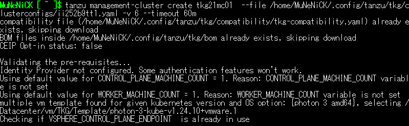
Verifying the Management cluster deployment
Deployment is complete when a success message is displayed in the web UI or Bootstrap machine log.
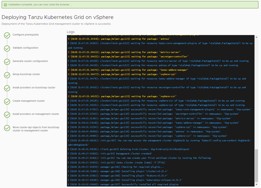
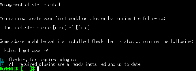
Verifying deployment with kubectl
You can check the deployment by running the following command shown in the Bootstrap machine log.
MuNeNiCK [ ~ ]$ kubectl get apps -ACheck vCenter
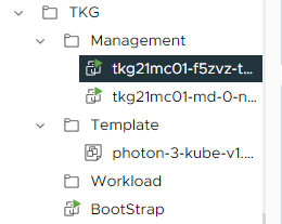
Log in to vCenter Server and confirm that the virtual machines were created in “TKG” → “Management”.
Check NSX ALB
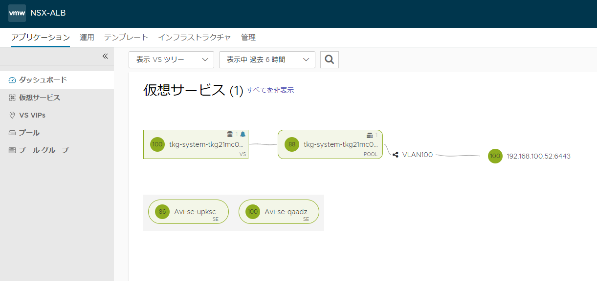
You can verify the deployment by logging in to NSX ALB and opening Applications → Dashboard. To display it like the image, change “VS List” in the upper left to “VS Tree”.
Saving the Management cluster YAML
The YAML created here will also be used for the Workload cluster, so save it with the steps below.
- Run the command below and confirm that the YAML file exists.
MuNeNiCK [ ~ ]$ ls -al $HOME/.config/tanzu/tkg/clusterconfigs/
total 20
drwx------ 2 MuNeNiCK users 4096 May  9 22:07 .
drwx------ 7 MuNeNiCK users 4096 May  9 23:00 ..
-rw------- 1 MuNeNiCK users 4459 May  9 22:00 ii252b9tt1.yaml
-rw------- 1 MuNeNiCK users 3317 May 10 00:13 tkg21mc01.yaml- Run the command below and save the YAML file to your home directory. *The YAML file name changes depending on the environment, so adjust it as needed.
MuNeNiCK [ ~ ]$ cp $HOME/.config/tanzu/tkg/clusterconfigs/ii252b9tt1.yaml tkg21mc01.yaml- Run the following command and confirm that it was copied.
MuNeNiCK [ ~ ]$ ls -l $HOME
total 313612
drwxr-x--- 2 MuNeNiCK users      4096 May  9 20:27 bin
drwxr-x--- 3 MuNeNiCK users      4096 Mar  9 09:42 cli
-rwxrwxrwx 1 MuNeNiCK users  46067712 Apr 23 20:34 kubectl-linux-v1.24.10+vmware.1
-rwxrwxrwx 1 root     root  275052656 Apr 23 20:34 tanzu-cli-bundle-linux-amd64.tar.gz
-rw------- 1 MuNeNiCK users      4459 May 10 08:49 tkg21mc01.yaml
Connecting to the Management cluster
Several operations are required to connect to the Management cluster and manage the cluster.
- First, run the command below to get the kubeconfig.
MuNeNiCK [ ~ ]$ tanzu mc kubeconfig get --admin
Credentials of cluster 'tkg21mc01' have been saved
You can now access the cluster by running 'kubectl config use-context tkg21mc01-admin@tkg21mc01'- Next, run the command shown in the log output.
MuNeNiCK [ ~ ]$ kubectl config use-context tkg21mc01-admin@tkg21mc01
Switched to context "tkg21mc01-admin@tkg21mc01".- Check the current context by running the command below.
MuNeNiCK [ ~ ]$ kubectl config get-contexts
CURRENT   NAME                        CLUSTER     AUTHINFO          NAMESPACE
* tkg21mc01-admin@tkg21mc01 tkg21mc01 tkg21mc01-admin- Verify the nodes in the current context with the following command.
MuNeNiCK [ ~ ]$ kubectl get nodes
NAME                                    STATUS   ROLES           AGE   VERSION
tkg21mc01-f5zvz-tq8wn                   Ready    control-plane   8h    v1.24.10+vmware.1
tkg21mc01-md-0-n85gx-6f5bf77dc8-lv58j   Ready    <none>          8h    v1.24.10+vmware.1
This completes the Management cluster build and connection steps.
Building a Workload Cluster
Creating YAML for the Workload cluster
- Copy the Management cluster YAML that you copied to your home directory earlier.
MuNeNiCK [ ~ ]$ cp tkg21mc01.yaml tkg21wc01.yaml
MuNeNiCK [ ~ ]$ ls -l
total 313620
drwxr-x--- 2 MuNeNiCK users      4096 May  9 20:27 bin
drwxr-x--- 3 MuNeNiCK users      4096 Mar  9 09:42 cli
-rwxrwxrwx 1 MuNeNiCK users  46067712 Apr 23 20:34 kubectl-linux-v1.24.10+vmware.1
-rwxrwxrwx 1 root     root  275052656 Apr 23 20:34 tanzu-cli-bundle-linux-amd64.tar.gz
-rw------- 1 MuNeNiCK users      4459 May 10 08:49 tkg21mc01.yaml
-rw------- 1 MuNeNiCK users 4459 May 10 08:57 tkg21wc01.yaml-
Edit the following items with vi or another editor. *This is only an example, so change it for your environment.
- CLUSTER_NAME: Change this to the Workload cluster name. This article uses “tkg21wc01”.
- VSPHERE_FOLDER: Change this to the Workload cluster folder. This article uses “/Datacenter/vm/TKG/Workload”.
-
Option 1: Change the Workload cluster deployment type from “Development” to “Production” by editing the following item. *If you apply this setting, 6 virtual machines will be deployed. Use it only if you have sufficient resources.
- CLUSTER_PLAN: Change from “dev” to “prod”.
-
Option 2: Use Autoscaler to automatically adjust the Kubernetes cluster size. Add the following code to the end of the YAML file. *This Autoscaler can only be configured for Workload clusters.
#! ---------------------------------------------------------------------
#! Autoscaler related configuration
#! ---------------------------------------------------------------------
ENABLE_AUTOSCALER: true
AUTOSCALER_MAX_NODES_TOTAL: "0"
AUTOSCALER_SCALE_DOWN_DELAY_AFTER_ADD: "10m"
AUTOSCALER_SCALE_DOWN_DELAY_AFTER_DELETE: "10s"
AUTOSCALER_SCALE_DOWN_DELAY_AFTER_FAILURE: "3m"
AUTOSCALER_SCALE_DOWN_UNNEEDED_TIME: "10m"
AUTOSCALER_MAX_NODE_PROVISION_TIME: "15m"

# Each min/max pair (0,1,2) corresponds to an availability zone.
# If you have a 'dev' cluster, you only need to fill in the min/max size for '0'.
# If you have a 'prod' cluster, you need to fill in all three pairs.
AUTOSCALER_MIN_SIZE_0: 1
AUTOSCALER_MAX_SIZE_0: 5
AUTOSCALER_MIN_SIZE_1: 1
AUTOSCALER_MAX_SIZE_1: 5
AUTOSCALER_MIN_SIZE_2: 1
AUTOSCALER_MAX_SIZE_2: 5-
ENABLE_AUTOSCALER: Enable or disable “Autoscaler”.
-
AUTOSCALER_MAX_NODES_TOTAL: Limit the total number of control-plane nodes and worker nodes. You can remove the restriction by specifying 0.
-
AUTOSCALER_SCALE_DOWN_DELAY_AFTER_ADD: The amount of time the cluster autoscaler waits after a scale-up operation before restarting the scale-down scan.
-
AUTOSCALER_SCALE_DOWN_DELAY_AFTER_DELETE: The amount of time the cluster autoscaler waits before restarting the scale-down scan after removing a node.
-
AUTOSCALER_SCALE_DOWN_DELAY_AFTER_FAILURE: The amount of time the cluster autoscaler waits before restarting the scale-down scan after a failed scale-down.
-
AUTOSCALER_SCALE_DOWN_UNNEEDED_TIME: The amount of time the cluster autoscaler must wait before scaling down a target node.
-
AUTOSCALER_MAX_NODE_PROVISION_TIME: Maximum time the cluster autoscaler waits to provision a node.
-
AUTOSCALER_*_SIZE: For clusters with a single worker node, such as a
devcluster, only setAUTOSCALER_MIN_SIZE_0andAUTOSCALER_MAX_SIZE_0. If there are multiple control-plane nodes, such as with “prod”, configure settings for each control-plane node.- AUTOSCALER_MIN_SIZE_*: Minimum number of worker nodes. This article sets it to “1”.
- AUTOSCALER_MAX_SIZE_*: Maximum number of worker nodes when automatic scaling is performed. This article sets it to “5”.
-
Run the following command to check the configuration file.
MuNeNiCK [ ~ ]$ diff tkg21mc01.yaml tkg21wc01.yaml
21,22c21,22
< CLUSTER_NAME: tkg21mc01
< CLUSTER_PLAN: dev
---
> CLUSTER_NAME: tkg21wc01
> CLUSTER_PLAN: prod
59c59
< VSPHERE_FOLDER: /Datacenter/vm/TKG/Management
---
> VSPHERE_FOLDER: /Datacenter/vm/TKG/Workload
71a72,91
> #! ---------------------------------------------------------------------
> #! Autoscaler related configuration
> #! ---------------------------------------------------------------------
> ENABLE_AUTOSCALER: true
> AUTOSCALER_MAX_NODES_TOTAL: "0"
> AUTOSCALER_SCALE_DOWN_DELAY_AFTER_ADD: "10m"
> AUTOSCALER_SCALE_DOWN_DELAY_AFTER_DELETE: "10s"
> AUTOSCALER_SCALE_DOWN_DELAY_AFTER_FAILURE: "3m"
> AUTOSCALER_SCALE_DOWN_UNNEEDED_TIME: "10m"
> AUTOSCALER_MAX_NODE_PROVISION_TIME: "15m"
>
> # Each min/max pair (0,1,2) corresponds to an availability zone.
> # If you have a 'dev' cluster, you only need to fill in the min/max size for '0'.
> # If you have a 'prod' cluster, you need to fill in all three pairs.
> AUTOSCALER_MIN_SIZE_0: 1
> AUTOSCALER_MAX_SIZE_0: 5
> AUTOSCALER_MIN_SIZE_1: 1
> AUTOSCALER_MAX_SIZE_1: 5
> AUTOSCALER_MIN_SIZE_2: 1
> AUTOSCALER_MAX_SIZE_2: 5
Deploying a Workload cluster
- Run the following command. It likely will not deploy on the first run because TKG 2.1 converts the old YAML format.
MuNeNiCK [ ~ ]$ tanzu cluster create -f tkg21wc01.yaml
Validating configuration...
Warning: Pinniped configuration not found; Authentication via Pinniped will not be set up in this cluster. If you wish to set up Pinniped after the cluster is created, please refer to the documentation.

Legacy configuration file detected. The inputs from said file have been converted into the new Cluster configuration as '/home/MuNeNiCK/.config/tanzu/tkg/clusterconfigs/tkg21wc01.yaml'

To create a cluster with it, use
tanzu cluster create --file /home/MuNeNiCK/.config/tanzu/tkg/clusterconfigs/tkg21wc01.yaml- Run the command shown under “To create a cluster with it, use” in the log. This starts the Workload cluster deployment.
MuNeNiCK [ ~ ]$ tanzu cluster create --file /home/MuNeNiCK/.config/tanzu/tkg/clusterconfigs/tkg21wc01.yaml
Validating configuration...
Warning: Pinniped configuration not found; Authentication via Pinniped will not be set up in this cluster. If you wish to set up Pinniped after the cluster is created, please refer to the documentation.
creating workload cluster 'tkg21wc01'...
If your Workload cluster deployment fails
- Run the following command to delete the Workload cluster.
MuNeNiCK [ ~ ]$ tanzu cluster delete tkg21wc01
Deleting workload cluster 'tkg21wc01'. Are you sure? [y/N]: y
successfully deleted autoscaler resources from management cluster
Workload cluster 'tkg21wc01' is being deleted- Run the following command and confirm that it was deleted.
MuNeNiCK [ ~ ]$ tanzu cluster list
NAME NAMESPACE STATUS CONTROLPLANE WORKERS KUBERNETES ROLES PLAN TKR- Review the settings and server status, then try deploying the cluster again. You can also specify the
--timeout <time>option.
Verifying Workload Cluster Deployment
Checking the logs on the Bootstrap machine
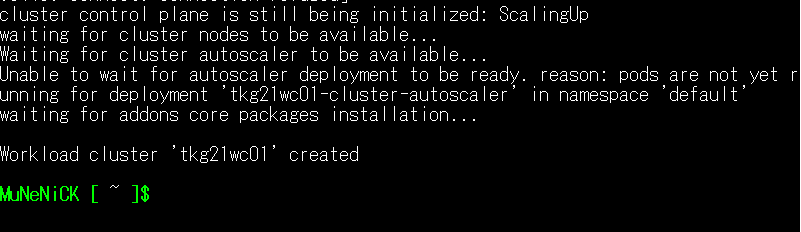
- If “Workload cluster ‘tkg21wc01’ created” is displayed in the log on the Bootstrap machine, the deployment was successful.
Check with the Tanzu CLI
- Access your Bootstrap machine and run the command below.
MuNeNiCK [ ~ ]$ tanzu cluster list
  NAME       NAMESPACE  STATUS   CONTROLPLANE  WORKERS  KUBERNETES         ROLES   PLAN  TKR
  tkg21wc01  default    running  3/3           3/3      v1.24.10+vmware.1  <none>  prod  v1.24.10---vmware.1-tkg.2
Check vCenter
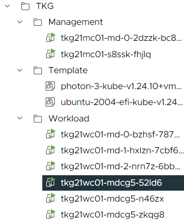
- Access vCenter Server and confirm that the virtual machines were created in the “TKG” → “Workload” folder.
Check NSX ALB
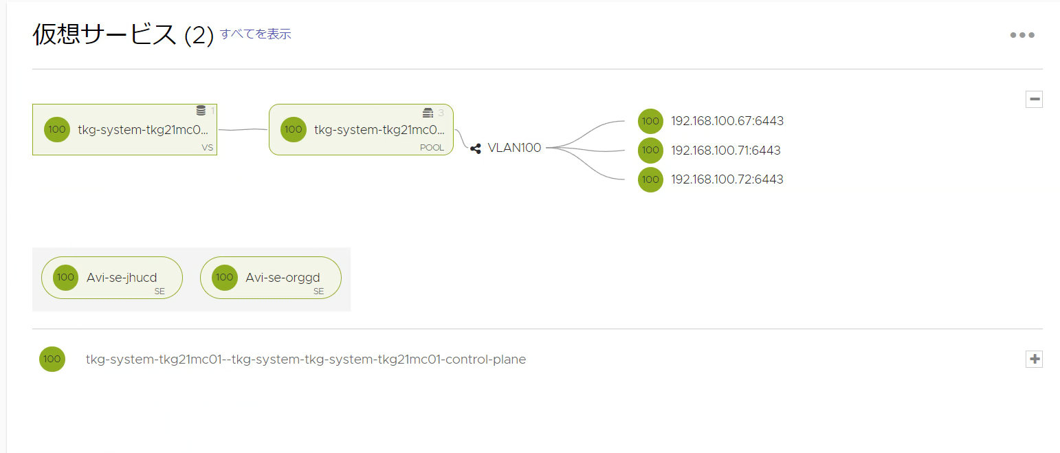
- You can check the deployment by logging in to NSX ALB and opening Applications → Dashboard.
Connecting to a Workload cluster
Several operations are required to connect to the Workload cluster and manage the cluster.
- First, run the command below to get the kubeconfig.
MuNeNiCK [ ~ ]$ tanzu cluster kubeconfig get tkg21wc01 --admin
Credentials of cluster 'tkg21wc01' have been saved
You can now access the cluster by running 'kubectl config use-context tkg21wc01admin@tkg21wc01'- Next, run the command shown in the log output.
MuNeNiCK [ ~ ]$ kubectl config use-context tkg21wc01-admin@tkg21wc01
Switched to context "tkg21wc01-admin@tkg21wc01".- Check the current context by running the command below.
MuNeNiCK [ ~ ]$ kubectl config get-contexts
CURRENT   NAME                        CLUSTER     AUTHINFO          NAMESPACE
          tkg21mc01-admin@tkg21mc01   tkg21mc01   tkg21mc01-admin
* tkg21wc01-admin@tkg21wc01 tkg21wc01 tkg21wc01-admin- Verify the nodes in the current context with the following command.
MuNeNiCK [ ~ ]$ kubectl get nodes
NAME                                    STATUS   ROLES           AGE     VERSION
tkg21wc01-md-0-bzhsf-7876ffdcb7-8nkg8   Ready    <none>          8h      v1.24.10+vmware.1
tkg21wc01-md-1-hxlzn-7cbf69bd58-4tqjc   Ready    <none>          8h      v1.24.10+vmware.1
tkg21wc01-md-2-nrn7z-6bb84c66c-gxjgx    Ready    <none>          8h      v1.24.10+vmware.1
tkg21wc01-mdcg5-52ld6                   Ready    control-plane   8h      v1.24.10+vmware.1
tkg21wc01-mdcg5-n46zx                   Ready    control-plane   7h53m   v1.24.10+vmware.1
tkg21wc01-mdcg5-zkqg8                   Ready    control-plane   8h      v1.24.10+vmware.1
Check Pod behavior
Perform the following steps to confirm that your Workload cluster and NSX ALB are working properly.
- Run the command below to create a test Pod.
MuNeNiCK [ ~ ]$ kubectl run hello --image=gcr.io/google-samples/node-hello:1.0
pod/hello created- Check whether the Pod has started with the command below. It may take a few minutes to start.
MuNeNiCK [ ~ ]$ kubectl get pods
NAME    READY   STATUS    RESTARTS   AGE
hello 1/1 Running 0 101s- Run the following command to create a Service for the Pod so it can be accessed through the NSX ALB load balancer.
MuNeNiCK [ ~ ]$ kubectl expose pod hello --type=LoadBalancer --port=80 --target-port=8080
service/hello exposed- Check the Service status and assigned External-IP address with the following command.
MuNeNiCK [ ~ ]$ kubectl get service hello
NAME    TYPE           CLUSTER-IP      EXTERNAL-IP       PORT(S)        AGE
hello LoadBalancer 100.65.13.125 192.168.100.105 80:31362/TCP 108s-
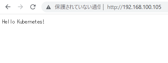
Open a browser and access the IP address you checked earlier. If you can access it, the Workload cluster and NSX ALB load balancer are working properly.
-
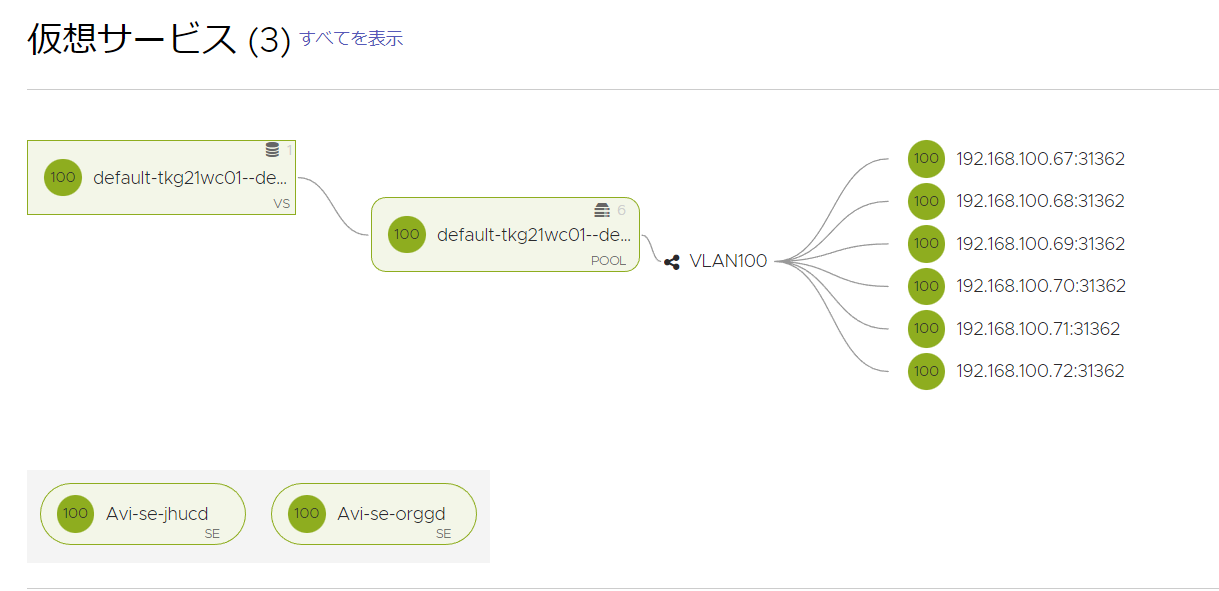
You can also check by logging in to NSX ALB and opening “Application” → “Dashboard”.
-
Finally, run the following command to delete the Pod and Service. When they are deleted, the NSX ALB virtual services are also deleted automatically.
MuNeNiCK [ ~ ]$ kubectl delete pod hello
pod "hello" deleted
MuNeNiCK [ ~ ]$ kubectl get pod
No resources found in default namespace.
MuNeNiCK [ ~ ]$ kubectl delete service hello
service "hello" deleted
MuNeNiCK [ ~ ]$ kubectl get service hello
Error from server (NotFound): services "hello" not found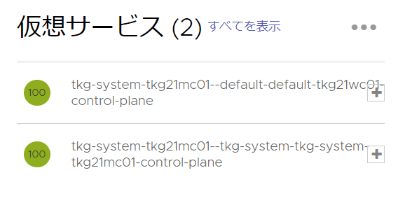
Autoscaler settings (optional)
If you configure Autoscaler settings, complete this section.
- Run the following command to switch to the Management cluster context.
MuNeNiCK [ ~ ]$ kubectl config use-context tkg21mc01-admin@tkg21mc01
Switched to context "tkg21mc01-admin@tkg21mc01".- Run the command below and check the MachineDeployment names.
MuNeNiCK@BootStrap [ ~ ]$ kubectl get md
NAME                 CLUSTER   REPLICAS   READY   UPDATED   UNAVAILABLE   PHASE     AGE   VERSION
tkgwc01-md-0-24cdt   tkgwc01   1          1       1         0             Running   14h   v1.25.7+vmware.2
tkgwc01-md-1-85fmf   tkgwc01   1          1       1         0             Running   14h   v1.25.7+vmware.2
tkgwc01-md-2-wfhc7 tkgwc01 1 1 1 0 Running 14h v1.25.7+vmware.2- Specify the minimum number of deployments for each MachineDeployment with the command below.
kubectl annotate machinedeployment MD-NAME cluster.k8s.io/cluster-api-autoscaler-node-group-min-size="MIN-SIZE"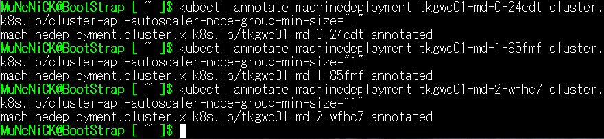
- Specify the maximum number of deployments for each MachineDeployment with the command below.
kubectl annotate machinedeployment MD-NAME cluster.k8s.io/cluster-api-autoscaler-node-group-max-size="MAX-SIZE"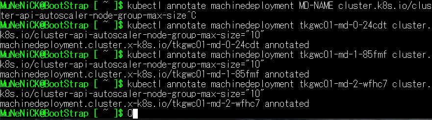
- Run the following command and confirm that the Autoscaler deployment is Ready at 1/1.
MuNeNiCK@BootStrap [ ~ ]$ kubectl get deployment
NAME                         READY   UP-TO-DATE   AVAILABLE   AGE
tkgwc01-cluster-autoscaler   1/1     1            1           14h
This completes the operation check for the TKG cluster and NSX ALB.
Next time
Because the Bootstrap machine is temporary, it is usually deleted after the Management cluster and Workload cluster are deployed. Therefore, you should create a separate machine to run the Tanzu CLI and manage both clusters. Next time, I will show how to run the Tanzu CLI on a separate machine and manage the clusters. Do not remove the Bootstrap machine at this stage yet.
Sites I referred to
- Getting started with Tanzu Kubernetes Grid. Part-04: Creation of Management Cluster
- Getting started with Tanzu Kubernetes Grid. Part-05: Creating Workload Cluster
- Building a lab with Tanzu Kubernetes Grid and NSX ALB.
- Simple deployment procedure of TKG 1.4.0 with NSX-ALB to vSphere environment
- Cluster Scaling